
Abstract
Sensory receptors in human skin transmit a wealth of tactile and thermal signals from external environments to the brain. Despite advances in our understanding of mechano- and thermosensation, replication of these unique sensory characteristics in artificial skin and prosthetics remains challenging. Recent efforts to develop smart prosthetics, which exploit rigid and/or semi-flexible pressure, strain and temperature sensors, provide promising routes for sensor-laden bionic systems, but with limited stretchability, detection range and spatio-temporal resolution. Here we demonstrate smart prosthetic skin instrumented with ultrathin, single crystalline silicon nanoribbon strain, pressure and temperature sensor arrays as well as associated humidity sensors, electroresistive heaters and stretchable multi-electrode arrays for nerve stimulation. This collection of stretchable sensors and actuators facilitate highly localized mechanical and thermal skin-like perception in response to external stimuli, thus providing unique opportunities for emerging classes of prostheses and peripheral nervous system interface technologies.
Introduction
Skin-based mechanoreceptors and thermoreceptors gather rich streams of information from the external environment1. The central and autonomic nervous systems analyze and transform these sensory inputs into regulated physiological responses and motor outputs1. Although there have been significant progresses in understanding the neural circuits underlying mechanical and thermal sensation2, replicating these capabilities in artificial skin and prosthetics remains challenging. As a result, many amputee patients wear prosthetic limbs for cosmetic utility3 or as supplementary movement aids4 rather than as a functional replacement for natural limbs. Recent advances in the design of prosthetic limbs integrated with rigid and/or semi-flexible tactile sensors provide sensory reception to enable feedback in response to variable environments5. However, there still exists a mechanical mismatch between conventional electronics in wearable prosthetics and soft biological tissues, which impede the utility and performance of prosthetics in amputee populations.
Several efforts are underway to bridge the technological gap between artificial and real skin. Flexible and/or stretchable tactile sensors based on various micro/nano materials and structures have been the focus of intense study6,7,8,9,10,11. In particular, pressure-sensitive rubbers (PSRs) are used as resistive elements that respond to tensile strains12,13,14, which can be integrated with flexible organic electronics15,16,17,18 and nanomaterial-based (nanowires19 and nanotubes20) transistors. However, conventional PSRs have modest response times and undergo significant hysteresis. Single crystalline silicon strain gauges on soft elastomer exhibit a linear relationship between strain and relative resistance changes with fast response times21. These sensors have been previously utilized to detect motion across various anatomical locations, such as the wrist22 and fingers23. In addition, stretchable metal and single crystalline silicon temperature sensors12,24 fabricated on ultrathin substrates have been applied for temperature monitoring on human skin. However, the heterogeneity in geometry and strain profiles of skin across different anatomies necessitate custom designs for specific body locations. Heterogeneous integration of pressure, temperature and humidity sensing coupled with electroresistive thermal actuation in site-specific geometrical layouts would thus provide unique opportunities to dramatically advance the state of the art in smart prosthetics and artificial skin.
Here we report a stretchable prosthetic skin equipped with ultrathin single crystalline silicon nanoribbon (SiNR) strain, pressure and temperature sensor arrays. The SiNR sensor arrays have geometries that are tuned to stretch according to the dynamic mechanical properties of the target skin segment. This design strategy provides the highest levels of spatio-temporal sensitivity and mechanical reliability, thereby dramatically enhancing the perception capabilities of artificial skin in response to highly variable external environments. Integration of stretchable humidity sensors and heaters further enables the sensation of skin moisture and body temperature regulation, respectively. Corresponding electrical stimuli can then be transmitted from the prosthetic skin to the body to stimulate specific nerves via conformally contacted ultrathin stretchable nanowire-based electrodes, which are decorated with ceria nanoparticles for inflammation control.
Results
Artificial skin with multi-modal sensing capability
Figure 1a shows an image of artificial skin with integrated electronics laminated on the surface of a prosthetic hand. The artificial skin surface of the prosthesis is highly compliant (inset), and mechanically couples to the curvilinear surface of the prosthesis. A schematic illustration of the stacked layers (Fig. 1b) highlights the location of the embedded electronics, sensors and actuators, with magnified views shown in Fig. 1c–f.
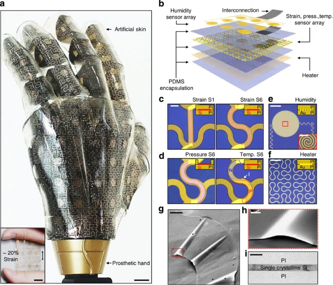
(a) Photograph of a representative smart artificial skin with integrated stretchable sensors and actuators covering the entire surface area of a prosthetic hand. Scale bar, 1 cm. The inset shows the artificial skin stretched ~20%. Scale bar, 1 cm. (b) An exploded view of the artificial skin comprised of six stacked layers. Interconnected wires of each layer relay signals to external instruments. (c) Representative microscopic images of SiNR strain gauge: S1 which has a curvature of 0 mm−1 (left); S6 which has a curvature of 10 mm−1 (right). S1 and S6 are optimized for the location of minimal stretch (~5%) and large stretch (~30%), respectively. Scale bar, 10 μm. (d) Representative microscopic images of SiNR pressure sensor S6 and temperature sensor S6. (e) Microscopic image of humidity sensor. Scale bar, 2 mm. Bottom right inset shows the magnified view of the central area, showing separate electrodes with identical inter-spiral gap. Scale bar, 0.5 mm. (f) Microscopic image of electroresistive heater. Scale bar, 4 mm. (c–f) The upper right insets of each figure show the cross-sectional structure of each device. (g) Scanning electron microscope image of the SiNR transferred on the silicon oxide substrate. The wrinkles are deliberately formed to show the SiNR’s high flexibility. Scale bar, 20 μm. (h) The magnified view of wrinkled SiNR. Scale bar, 2 μm. (i) A cross-sectional transmission electron microscope image of the strain gauge, showing that the SiNR encapsulated with PI layers is located at the neutral mechanical plane. Scale bar, 200 nm. Press., pressure; temp., temperature.
The bottom layer contains electroresistive heaters in filamentary patterns bonded to the polydimethylsiloxane (PDMS, Dow Corning, USA) substrate. These thermal actuators are in fractal-inspired formats25 (Fig. 1f) to facilitate uniform heating during stretching and contraction of the skin layer. To monitor tactile and thermal feedback during actuation, we employ strain (Fig. 1c), pressure (Fig. 1d left) and temperature sensor (Fig. 1d right) arrays in the middle layer of the stack. These network of sensors have spatially varying geometrical designs, ranging from linear to serpentine shapes (denoted as S1–S6 in ascending order of curvatures, Supplementary Fig. 1), depending on the mechanics of the underlying prosthetics. An array of humidity sensors, consisting of coplanar capacitors (Fig. 1e) in the top encapsulating layer detects capacitance changes at different humidity levels (Fig. 1e bottom right, inset shows the magnified view) to capture information about ambient conditions. Each sensor/actuator layer has distinct interconnections to the external data acquisition instrument (Fig. 1b). Integration of each stacked layer using via-hole structures can further simplify the wiring requirements. Due to this stacked structure configuration, sensor arrays may mechanically interfere with each other. For instance, strain/pressure sensors positioned beneath humidity sensors could exhibit reduced mechanical responses to external deformations because of the additional stiffness. To address this issue, stacked structures with staggered arrangement of sensors provide a possible solution to minimize interferences.
All of the aforementioned devices have ultrathin regions, that is, SiNRs or gold (Au) NRs that are passivated by polyimide (PI; Fig. 1c–f upper right inset). The one exception is the design of the tactile pressure sensors, which contain a cavity to enhance sensitivity in response to mechanical pressure changes. The key material utilized in the fabrication of these tactile sensors is p-type doped single crystalline SiNRs (Supplementary Fig. 2), which have both high piezoresistivity (gauge factor: ~200; ref. 21) and low fracture toughness (~1.0 MPa m1/2; ref. 26). To prevent mechanical failures, we employ mechanical strategies, whereby ultrathin (~110 nm) SiNRs are kept in the neutral mechanical plane of the stack27. Figure 1g shows a scanning electron microscope image of a crack-free SiNR transferred on the silicon oxide substrate. Wrinkles are deliberately induced to highlight the ultrathin nature and mechanical flexibility of the SiNR under mechanical deformation (Fig. 1h). Figure 1i shows a cross-sectional transmission electron microscope image of the SiNR located in the neutral mechanical plane (PI/SiNR/PI structure). These designs help to minimize bending induced strains27.
Detection of regional strain of skins in various motions
Skin normally experiences multi-axial forces and undergoes a range of angular and linear motions at different body locations. This heterogeneity in movements and strains of skin suggests the need for location-specific optimization of sensors and actuators in artificial skin and prosthetics. For example, a network of tactile sensors and strain gauges can provide feedback about tensile strains to characterize fatigue or ensuing failure modes in a highly localized manner.
To characterize the mechanical behaviour of movements and skin mechanics on the arm and hands, we capture movement and strains from several target points (Supplementary Fig. 3) on skin using a motion-capture camera system (Fig. 2a, Supplementary Note 1). In total, 12 motion-capture cameras (OptiTrack Prime 41, NaturalPoint, USA) are synchronously used to acquire three-dimensional coordinates of reflective markers affixed to the hand and wrist. Four representative hand movements, including fist clenching as well as vertical (bending) and lateral (tilting) wrist movements are analyzed (Fig. 2b). Strain distribution is calculated by measuring displacements relative to neighbouring reflective markers. During fist clenching, the skin stretches ~5% (Fig. 2b upper left), whereas, significantly greater strains (~16%) are induced in response to bending (Fig. 2b upper right). Tilting movements induce compression on the wrinkled side of the wrist, while skin experiences stretching on the opposing side of the wrist (Fig. 2b bottom).

(a) Schematic image of motion-capture system. (b) Regional strain maps of the skin, calculated using positional information acquired by motion-capture system for four different motions: clenching fist, front bending, tilting left and right. An upper left inset of each case shows the actual hand with reflective markers. (c) Map of maximum stretching range for entire area acquired by combining the data from b, and corresponding arrangement of site-specifically designed SiNR strain gauge. The frames on the right show magnified views of each design (S1, S3 and S6 designs; indicated with black boxes). (d) Image of the fabricated site-specifically designed SiNR strain gauge arrays conformally attached on the back of hand. Scale bar, 2 cm. The frames on the right show magnified views of each design (indicated with white boxes). S1, S3 and S6 design for low, medium and high deformation location, respectively. Deform., deformation; med., medium.
By gathering these movement data, we map strain profiles near the wrist and hand (Fig. 2c). For regions where skin hardly stretches, linear SiNR (S1 design) is used to maximize sensitivity. On the other hand, serpentine SiNRs (for example, S3 or S6 designs) are applied on more stretchy areas, to accommodate the larger range of strain changes. Furthermore, the curvature of SiNRs are optimally designed depending on the stretchability of the underlying anatomy (for example, low deformation region ~5%: S1 design, medium deformation region ~10%: S3 design, high deformation region ~16%: S6 design, right frames of Fig. 2c). These site-specific SiNR sensor arrays are shown in Fig. 2d. The exploded frames to the right are magnified images of each design. These ultrathin filamentary designs enable conformal integration on human skin with high sensitivity and mechanical durability. Detailed step-by-step fabrication procedures are included in Supplementary Fig. 4 and Methods section.
SiNR mechanical sensors with site-specific sensitivity
To characterize the effects of strains on different SiNR sensor designs, we examine six unique serpentine designs (Fig. 3a left) with curvatures of κ=0 (S1), 1.94 (S2), 4.74 (S3), 7.4 (S4), 9.75 (S5) and 10 mm−1 (S6). An experimental stretch test setup using a custom-made bending stage is shown in Supplementary Fig. 5a. Figure 3a (top frames) shows an array of SiNR strain gauges exposed to a range of applied strains (0, 15 and 30%). The bottom frames show finite element analysis (FEA) results (Supplementary Note 2). As applied strains increase, SiNR strain gauges with small curvature experience considerably greater strains compared with those with larger curvatures. The serpentine designs of large curvature help to relieve induced strains more than smaller ones. This effect is captured by measuring relative resistance (ΔR/R) as a function of applied strain (Fig. 3b left).

(a) Sequential images of SiNR strain gauges (top frames) under different applied strains (0, 15 and 30%) and corresponding FEA results (bottom frames). Scale bar, 1 mm. (b) The resistance changes for different curvatures of SiNR, depending on applied strain (left) and temporal resistance changes of different curvature of SiNR under cyclical stretching (right). (c) Regionally mapped per cent resistance changes, measured by site-specifically designed strain gauge arrays (S1 for minimal stretch region and S6 for large stretch region). Mapped regions are indicated with red dotted box for four different motions. Scale bar, 2 cm. (d) Schematics showing the working principle of the SiNR pressure sensor with a cavity (top left) compared with the SiNR pressure sensor without a cavity (bottom left), scanning electron microscope images of the device's cross-section with a cavity (top middle) and without one (bottom middle) and FEA results (top right; bottom right). Scale bar, 500 nm. (e) The resistance changes of a pressure sensor with a cavity (black) and without a cavity (red) with respect to the applied pressure for different design of the SiNR (S1: graph on the left, S6: graph on the right). (f) Regionally mapped per cent resistance changes measured by pressure sensor array of S6 for gradually increasing pressure. Princi., principle; Stretch., stretching.
SiNR sensors of larger curvature can withstand greater applied strains, and thereby have large dynamic range, but exhibit reduced sensitivity (Fig. 3b). The SiNR S6 sustains strains up to ~30%, whereas S1 fractures at ~10% applied strain levels. But cyclic stretching tests reveal that sensitivity increases with smaller curvatures (Fig. 3b right). According to this tradeoff effect, SiNR S1 is most appropriate for sites with small range of stretching, whereas SiNR S6 is more suitable for regions experiencing large stretching. The results also indicate that SiNR strain gauges have a linear and fast response time, and no hysteresis irrespective of designs. The SiNR strain gauges are mainly sensitive to the longitudinal stretching (Supplementary Fig. 6a,b). Noise in the strain sensors is often caused by shift in external temperature, which affects individual strain sensor resistance measurements. To reduce effects of noise caused by thermal shifts, a Wheatstone bridge configuration can be applied (Supplementary Fig. 6c,d). In the future, it is necessary to incorporate strain gauges in rosette configurations28 to measure strain distribution in the arbitrary xy coordinate plane to characterize plane strain of prosthetic skin (Supplementary Fig. 7).
Site-specific designs for strain gauge arrays that conform to the complex geometry of the human hand (Fig. 2d, Supplementary Fig. 5b) are used to measure its strain distributions. Figure 3c shows strain distribution maps (red dotted box regions) in response to four representative hand motions. Signals are collected with a multiplexing measurement unit (Supplementary Fig. 5a,c, Supplementary Note 3). For locations where skin deformations are small (for example, back of hand; Fig. 2b upper left), the S1 designs are used (clenching fist; Fig. 3c upper left). Despite small induced strains on the back of hand, the SiNR strain gauge arrays with S1 design successfully map the regional strain distribution. Conversely, SiNR strain gauge arrays with S6 design are used in locations where large skin deformations occur (wrist region; Fig. 2b upper right and bottom), with significant bending (Fig. 3c upper right) and tilting (Fig. 3c bottom). The SiNR strain gauge arrays measure large induced strains with high fidelity. Even larger induced strains exist near knee joints and can be measured (Supplementary Fig. 8a,b). SiNR strain gauges having large curvatures (for example, S3) endure mechanical deformations in response to cyclic bending of knee joints more than small curvatures (for example, S1; Supplementary Fig. 8c).
Figure 3d shows the working principle of a SiNR pressure sensor. By designing a cavity in the PI passivation layer of SiNRs (Fig. 3d top versus bottom), the pressure detection sensitivity is enhanced, as confirmed by FEA (Fig. 3d upper right versus bottom right, Supplementary Note 4). The cavity-based SiNR pressure sensor shows ~10 times higher sensitivity to applied pressures (see experimental setup in Supplementary Fig. 9a) than the SiNR pressure sensor without the cavity for both S1 and S6 designs (Fig. 3e). Detailed measurements of sensitivity for S1 and S6 are 0.41% kPa−1 (with cavity) versus 0.0315% kPa−1 (without cavity) and 0.075% kPa−1 (with cavity) versus 0.0073% kPa−1 (without cavity), respectively. Serpentine-shaped SiNR pressure sensors (for example, S6) have reduced sensitivity to vertical pressures compared with linear versions (S1). However, the pressure sensitivity of S6 design sensors is comparable to human mechanoreceptors responses, which normally respond to stresses as low as ~87 kPa (ref. 1). Supplementary Fig. 9b and Fig. 3f show pressure response maps from sensor arrays with S1 and S6 designs, respectively. S1 design sensors are appropriate for the relatively less stretchy region where high tactile sensitivity is required such as fingertips. On the other hand, S6 design sensors are suitable for the relatively more elastic regions where modest tactile sensitivity is required, such as near the wrist. The S6 design pressure sensor shows stable pressure sensing sensitivity under external strains (Supplementary Fig. 9c).
SiNR temperature sensors and Au-based sensor/actuator
To measure temperature, SiNRs are doped twice to form p-n junctions (Fig. 1d right). Temperature sensors integrated onboard prosthetic skin should not be affected by mechanical deformations. Supplementary Fig. 10 shows I–V curves of distinctively designed temperature sensors (from S1 to S6 designs) at room temperature in response to applied strains. The divergence between each I–V curve under different strains is remarkably reduced as the curvature of sensors is increased (for example, S6). The large curvature of the sensors allows for stable temperature measurements under a wide range of stretching conditions. I–V curves of S1 and S6 temperature sensors are obtained at different temperatures under 0 and 10% applied strain (Supplementary Fig. 11). Figure 4a shows calibration curves obtained by extracting voltages at specific current (~10 nA) from I–V curves. The calibration curves for S1 design show the dramatic shifts in response to applied strain, whereas the S6 design exhibits minimal change. Temperature sensors with S6 design are used to minimize the effect of mechanical deformations on the temperature sensing. The temperature sensor design with large curvature enables reliable temperature monitoring under various applied pressures (Supplementary Fig. 12). A temperature distribution map is realized with these sensor arrays with and without local heating (Fig. 4b left and right, Supplementary Note 5). The temperature sensor array data streams are comparable to those collected with a commercial infrared (IR) camera as a control. To construct large area temperature sensor arrays, a multiplexing strategy is necessary to minimize the wiring number. SiNR diode temperature sensors have a significant advantage in their construction, owing to their nonlinear characteristics29. The spatial resolution of the multiplexed temperature sensor array of SiNR diodes is sufficiently high to accurately recognize the thermal profile of a heated object (Supplementary Fig. 13). Further increases in sensitivity can be achieved by incorporating novel nanomaterials/microstructures6,30.

(a) Calibration curves of SiNR temperature sensors of representative designs (S1: graph on the left and S6: graph on the right) under 10% stretched (red) and unstretched conditions (black). (b) Regionally mapped temperature measured by an IR camera and the SiNR temperature sensor array of S6 for initial condition (left) and partially heated condition (right). (c) A calibration curve of the coplanar humidity sensor (left) and double y-plot of the simultaneously measured temporal humidity change and the capacitance change of fabricated coplanar humidity sensor (right). (d) Image of water droplets covering the partial area of the coplanar humidity sensor array (left) and a corresponding map of regional capacitance change (right). Scale bar, 5 mm. (e) Heating capability of the heater. A fractal-inspired stretchable heater at 37 °C for emulating body temperature (left) and heated up to 58 °C (right). Scale bar, 5 mm. (f) Stretchability of heater. Heater is stretched from ~5% (left) to ~20% (right) with no degradation in heating performance. Cam., camera; sens., sensor; temp., temperature.
Although there is no specific biological receptor that senses skin exposure to humidity, human skin has the ability to sense changes in humidity with mechanoreceptors and thermoreceptors31. To mimic this capability, we fabricate stretchable capacitance-based humidity sensor arrays. Humidity sensing is performed in a test chamber with humidity control (Supplementary Fig. 14a left). The humidity sensor arrays detect capacitance changes induced by the permittivity change of PI, which absorbs water molecules (Supplementary Fig. 14a right inset). A calibration curve (Fig. 4c left) demonstrates this behaviour. The right frame of Fig. 4c shows that relative humidity changes measured with a commercial humidity sensor (blue) are well-matched to the capacitance changes measured with a fabricated humidity sensor (red). Spatial differences in humidity are discriminated (Fig. 4d, Supplementary Note 6). External disturbances, such as fingertip touch (Supplementary Fig. 14b), external strains (Supplementary Fig. 14c left) and temperature changes (Supplementary Fig. 14c right) have negligible effects on the humidity sensing.
For prosthetic devices and artificial skin to feel natural, their temperature profile must be controlled to match that of the human body. We thus fabricate stretchable thermal actuator arrays, whose thermal signature is readily controllable. The heater array can maintain body temperature (Fig. 4e left) or can be adjusted to higher temperatures (Fig. 4e right). Thermal actuation performance remains intact under various stretching conditions (~5 and ~20%; Fig. 4f).
Electronic skin responses in various daily life situations
The prosthetic hand and laminated electronic skin could encounter many complex operations such as hand shaking, keyboard tapping, ball grasping, holding a cup of hot/cold drink, touching dry/wet surfaces and human to human contact (Fig. 5). In the case of hand shaking, spatio-temporal strain can be mapped with SiNR strain gauge arrays. The strain map has high fidelity and captures minor shifts in strain near the index finger and respective joints (Fig. 5a). To investigate the performance of SiNR pressure sensors, we monitor temporal resistance changes in response to keyboard tapping (Fig. 5b top) and catching of a ball (Fig. 5b bottom). Pressure sensors show rapid and reliable responses to external stimuli in both situations. Temperature sensing is another important function of skin prosthesis. Temporal temperature monitoring is successfully done (red) once a hand touches a cup containing hot (Fig. 5c top) and cold (Fig. 5c bottom) liquid. Control temperature measurements are performed with an IR sensor (blue).

(a) Sequential images of prosthetic hand performing handshake. Scale bar, 2 cm. Spatio-temporal maps of resistance change of SiNR strain gauge arrays are overlapped at the corresponding locations on the back of hand. (b) An image of the prosthetic limb tapping keyboard (top left) and a plot for the corresponding temporal resistance change of the SiNR pressure sensor (top right). Scale bar, 10 cm. An image of the prosthetic limb catching a baseball (bottom left) and a plot for the corresponding temporal resistance change of the SiNR pressure sensor, showing dynamics of the prosthetic hand in grasping, maintaining and relaxing motions (bottom right). Scale bar, 5 cm. (c) Images of the prosthetic limb touching a cup of hot (top left) and iced water (bottom left), and plots for the corresponding temporal current change of the SiNR temperature sensor (PIN diode, red) and actual temperature trace measured by IR sensor (blue; top right: hot water, bottom right: iced water). Scale bar, 3 cm. (d) Images of baby doll with the dry (top left) and wet diaper (bottom left), and the prosthetic hand touching the dry (top middle) and wet diaper (bottom middle). Scale bar, 10 cm (top left). Scale bar, 5 cm (top middle). A bar plot of the capacitance value of the humidity sensor (right) before/after touching the dry (red)/wet (blue) diaper. (e) Images of the prosthetic limb caring a baby doll touching head (top left) and stomach (bottom left), IR camera images of heated prosthetic hand to the body temperature by the heater in the artificial skin (top middle, bottom middle). The heat remained high after detaching the prosthetic hand (top right, bottom right). Scale bar, 5 cm. Sens., sensor; temp., temperature.
Another application for smart prosthetics is sensing of dampness caused by fluid contact. Humidity sensors in the prosthetic skin provide feedback on the level of humidity and wetness (Fig. 5d top and bottom) in the representative example of a diaper. The measured capacitance differences between dry and wet cases are clearly distinguishable (Fig. 5d right). In addition, thermal actuators can provide the controlled heating to make the sense of touch from a prosthesis close to natural (Fig. 5e left). The artificial skin with the stretchable heater is warmed to ~36.5 °C (Fig. 5e middle) to mimic body temperature. The heat transfer to the baby doll is then captured with an IR camera (Fig. 5e right).
Relaying sensory signals to peripheral nerves
The ultimate goal of skin prosthesis is to enable amputees to feel various types of external stimuli. To achieve this goal, the signals captured across various sensor arrays must be processed and transmitted to stimulate the corresponding peripheral nervous system (Fig. 6a). For effective charge injection to peripheral nerves, low impedance in multi-electrode array (MEA)32 is critical. In addition, there are various mechanical motions of adjacent muscles, which require deformations of the interfacing electrodes to preserve mechanically conformal contacts and prevent scar formation arisen from mechanical mismatch between biological tissues and MEA33. Furthermore, inflammations at interfaces between electrodes and nerves induced by reactive oxygen species (ROS)34 must be suppressed, since massive inflammatory responses can cause death of nervous cells35 and damage the peripheral nervous system.

(a) An illustration showing a strategy of interconnecting the prosthetic skin to the peripheral nervous fibres using a stretchable MEA. Platinum nanowires (PtNWs) are grown on the Au electrodes with ceria nanoparticles adsorbed on the PtNWs (inset). (b) Scanning electron microscope image of PtNWs (left) and transmission electron microscope image of ceria nanoparticles decorated on a PtNW (right). Scale bar, 400 nm (left). Scale bar, 20 nm (right). Scale bar, 2 nm (right inset). (c) Impedance of Au, Pt/Au, PtNWs/Au electrodes with respect to frequency of applied signal (left), and ROS scavenging performance comparison between ceria nanoparticle embedded PtNWs/Au electrode and the PtNWs/Au electrode without ceria nanoparticles (right). The error bars in the figure are obtained by calculating s.d. from five samples of each case. (d) Images of the stretchable MEA (left) incorporating 34 independent contact electrodes (inset shows the magnified view) and MEA on peripheral nerves in muscle tissues of a rat model (right). Electrodes contacted to nerves are indicated with blue arrows. Scale bar, 2 mm (left). Scale bar, 0.5 mm (left inset). Scale bar, 2 mm (right). (e) Image of the stretchable MEA conformally wrapped on the nerve fibre of a rat model (left). Scale bar, 2 mm. The wrapped stretchable MEA maintains conformal contacts under deformations of the nerve fibre (inset). Blue arrows indicate electrodes contacted to nerves. FEA shows that serpentine-mesh type MEA has lower shear stress at interfaces than the planar-sheet type MEA (right). (f) Schematic drawing of the experimental setup for peripheral nerve stimulations based on pressure sensor signals and for electrophysiological signal recordings from the ventral posterolateral nucleus (VPL) of the thalamus in the right hemisphere (inset). (g) Measured signals from a pressure sensor in the prosthetic skin (black, top), simultaneously applied voltage to nerves according to sensed signals (red, middle) and delivered current through nerves (blue, middle). Corresponding electrophysiological responses recorded from the VPL of the thalamus in the right hemisphere (bottom). Conc., concentration; max., maximum; press., pressure.
To achieve low impedance, the MEAs are decorated with platinum nanowires (PtNWs; Fig. 6a inset and Fig. 6b left). PtNWs are grown using an electrochemical method with anodic aluminium oxide (AAO) nanostructures as templates. Ceria nanoparticles are adsorbed on PtNWs (Fig. 6b right) to suppress the ROS enrichment which is neurotoxic at high concentration34. The low material impedance of Pt and large surface area of NWs decreases impedance significantly lower than planar Au or Pt electrodes (Fig. 6c left). Ceria nanoparticles decorated on PtNWs successfully scavenge ROS (Fig. 6c right, red bar) compared with the control (Fig. 6c right, blue bar), which prevents ROS-induced inflammations36.
Figure 6d shows the fabricated stretchable MEA (left) conformally contacted on nerves (blue arrows) in muscle tissues (right). In a Sprague Dawley rat, the sciatic nerve is exposed for the current experiment after the gluteus muscles are dissected (Supplementary Note 7). The stretchable MEA is wrapped around the nerve fibre (Fig. 6e left) and maintains conformal contacts under deformations (Fig. 6e inset). The FEA (Fig. 6e right, Supplementary Note 8) shows that much lower shear stress is applied to the nerve fibre with the stretchable, serpentine-mesh type MEA (top) than the flexible, planar-sheet type MEA (bottom). The FEA mesh highlighting metal interconnections is shown in Supplementary Fig. 15. Mechanical-stress-induced inflammations37 can be prevented by virtue of the ceria nanoparticles adsorbed on the stretchable MEA.
In vivo electrophysiological recordings from the ventral posterolateral nucleus (VPL) are performed38,39 with recording electrodes positioned in the VPL of the thalamus (Anteroposterior: −2.3 mm, Medio-Lateral: 3.0 mm, Dorso-Ventral: −6.0 to −7.0 mm) in the right hemisphere (Fig. 6f, Supplementary Note 9). Signals from a pressure sensor (black) are obtained and processed as input voltage signals (red), which in turn, trigger the injection of current (blue) through a stretchable MEA (Fig. 6g top and middle, Supplementary Note 10). Evoked potentials from the rat’s VPL are simultaneously measured (Fig. 6g bottom). Synchronized sharp spikes are observed in the recorded electrophysiological signals in response to input signals from the pressure sensor, indicating successful electrical signal injection into the peripheral nerves and transfer to central nervous system. Necessary system components and signal flows for nerve stimulation40 are described in Supplementary Fig. 16. Despite advances in the nanomaterials-decorated stretchable neural interfaces, several safety issues are brought up, such as fractured PtNWs that may enter into the bloodstream, which should be clarified further. Inflammatory suppression effects of ceria nanoparticles on nerves also should be elucidated in the future by in vivo experiments.
Discussion
Site-specifically designed SiNR mechanical and temperature sensor arrays integrated with stretchable humidity sensors and thermal actuators enable high sensitivity, wide detection ranges and mechanical durability for prosthetic systems. Motion-capture videography provides a map of deformations of human skin in response to complex motions, thus forming the basis of site-specific geometries and designs for SiNR-based systems. Ultrathin layouts in neutral mechanical plane configurations further enhance durability and reduce risks of mechanical fractures. Interfacing stretchable electrodes decorated with PtNWs and ceria nanoparticles highlight the unique capability to merge these abiotic systems with the human body. As a result, sensing and actuation capabilities are enabled over a wide range of sensory inputs, in the presence of skin deformations, thus providing enhanced function and high performance in the emerging field of smart prosthetics.
Methods
Fabrication of SiNR-based devices
The fabrication begins with doping of silicon-on-insulator wafer with spin-on-dopant. The doped regions are transfer printed onto PI film coated on a silicon oxide (SiO2) wafer. Using reactive ion etching with photolithography, SiNRs are additionally patterned. Thermal evaporation for metallization (Au/Cr, 70 nm/7 nm), photolithography and wet-etching steps define the serpentine metal lines. Top PI layer is spin coated and the entire trilayer (PI/device/PI) is patterned by reactive ion etching. The whole device is transferred to the PDMS spin coated on the polyvinyl alcohol and encapsulated by another PDMS via spin coating. To attach devices to target substrates (for example, prosthetic hand), the encapsulated device is attached on the target position and then the polyvinyl alcohol film is removed through immersion in DI water.
Fabrication of Au-based devices
A precursor solution of PI is spin coated on a SiO2 wafer. The PI layer is fully cured at 250 °C for 1 h. To form separated electrodes for humidity sensors and resistive conduction paths for heaters, Au/Cr (70 nm/7 nm) layers are deposited by using thermal evaporation process. The deposited metal film is patterned through the photolithography. For the encapsulation, another PI layer is spin coated and cured using the same procedures and conditions. The whole structure (PI/metal/PI) is patterned as a stretchable form, released from the SiO2 wafer and then transferred to the polymeric substrate by using the same process with SiNR-based devices.
Characterization of SiNR strain gauges
The per cent resistance changes of SiNR strain gauges for different serpentine designs (S1–S6) are measured under various applied strains (Fig. 3b left). The resistance changes depending on the direction of the stretching are also analyzed (Supplementary Fig. 6a,b). The resistances of strain gauges are measured by using the source measurement units. Continuous resistance change monitoring of an individual SiNR strain gauge (Fig. 3b right) and output voltage monitoring from the Wheatstone bridge (Supplementary Fig. 6d) are performed by using the probe station (MSTECH, Korea) and parameter analyzer (B1500A, Agilent, USA).
Characterization of SiNR pressure sensors
Resistance change measurements for SiNR pressure sensors are recorded for representative serpentine designs (S1, S6) under various applied pressures (Fig. 3e). A screw having diameter of 0.5 cm is set on the load cell to press the specific region of the pressure sensor array (Supplementary Fig. 9a upper left inset). The load cell measures the applied load, and corresponding pressure can be calculated by dividing the load with the area. The resistance change induced by the applied pressure is calculated using the applied constant current (4 mA) and the corresponding voltage measured by the source measurement unit.
Characterization of SiNR temperature sensors
To obtain I–V curves of p–n-diode-based SiNR temperature sensors, electrodes connected to the p-type and n-type region are probed by using the probe station. The increasing voltage is applied to the p-type region while the n-type region is grounded, and the corresponding current is measured by the parameter analyzer. The calibration curves (Fig. 4a) are obtained by deducing the corresponding voltages at the specific current (10 nA) from the I–V curves shown in the Supplementary Fig. 11b,c and plotting them with respect to the temperatures measured by IR temperature sensor.
Characterization of humidity sensors
Relative humidity is controlled by introducing mixed streams of dry nitrogen and deionized water vapour in proper ratio into the test chamber (Supplementary Fig. 14a left). Relative humidity is measured with a commercial humidity temperature meter (CENTER 310) placed inside the test chamber. The capacitance changes of the fabricated humidity sensor are measured using a digital multimeter (NI PXI-4072, National Instruments, USA; Supplementary Fig. 5a) controlled with a custom-made LabVIEW programme.
Characterization of heaters
The stretchable heater (Au/Cr, 70 nm/7 nm, 550 Ω) on a PDMS substrate is connected to the power supply. The thermograms (Fig. 4e, f) is captured by a commercial IR camera (320 × 240 pixel; P25, FILR, Sweden). A manual bending stage is used to stretch the stretchable heater to apply designated amount of strain (Fig. 4f).
Synthesis of PtNWs on Au electrodes
H2PtCl6 (≥99.9% trace metals basis, Sigma-Aldrich) solution of 1% (w/w) containing 1.5 M HClO4 (70%, ACS reagent, Sigma-Aldrich) are prepared for the electrodeposition. A porous AAO template (Anodisc, Whatman) is laminated onto Au electrode array and dipped into the H2PtCl6 solution. A custom-made holder firmly fixes the AAO template on Au electrodes. Electrodepostion is performed by using the electrochemical workstation with the three-electrode system: a platinum, Ag/AgCl and Au electrode as a counter, reference and working electrode. Using potentiostatic mode with the potential of −0.35 V, electrodeposition is carried out for ~30 min at the room temperature. After the deposition is completed, the sample is washed with the triple-distilled water. Finally it is immersed into 1 M NaOH solution at room temperature for ~30 min to dissolve the AAO template.
Impedance characterization of conventional metal electrodes and PtNWs electrode
Thermally evaporated Au electrode, electrochemically deposited Pt film on Au electrode and electrochemically grown PtNWs on Au electrode are prepared. Impedance of each electrode is measured using electrochemical workstation with the three-electrode system: a platinum, Ag/AgCl and target electrode as a counter, reference and working electrode, respectively. All electrodes are immersed in the conductive PBS solution, therefore they are electrically connected to each other. Using AC impedance mode with the frequency range of 1 to 106 Hz, impedance characterization is carried out for ~5 min at the room temperature.
Synthesis of ceria nanoparticles
We add 1 mmol (0.4 g) of cerium (III) acetate (98%, Sigma-Aldrich) and 12 mmol (3.2 g) of oleylamine (~C18-content of 80–90%, AcrosOrganics) to 15 ml xylene (98.5%, Sigma-Aldrich). The mixed solution is treated by the sonicator for ~15 min at room temperature and then heated to 90 °C. Deionized water (1 ml) is injected into the solution under vigorous stirring at 90 °C, and then the solution colour changes to an off-white colour, representing that the reaction had occurred. The resulting mixture is aged at 90 °C for 3 h to give a light yellow colloidal solution, which is then cooled to room temperature. Acetone (100 ml) is added to the precipitated ceria nanoparticles. The precipitate is washed with acetone using centrifugation and the resulting ceria nanoparticles are easily dispersible in chloroform.
Synthesis of phospholipid-PEG-capped ceria nanoparticles
To make biocompatible ceria nanoparticles, ceria nanoparticles dispersed in chloroform are encapsulated by polyethlene glycol (PEG)-phospholipid shells. First, 5 ml ceria nanoparticles in CHCl3 (10 mg ml−1) is mixed with 35 ml CHCl3 solution containing 30 mg of mPEG-2000 PE. Then, solvents are evaporated by the rotary evaporator and incubated at 70 °C in vacuum for 1 h for entire chloroform removal. The addition of 5 ml water resulted in a clear and light-yellowish suspension. After filtration, excess mPEG-2000 PE is removed using ultracentrifugation. Purified phospholipid-PEG-capped ceria nanoparticles are dispersed in distilled water.
Anti-oxidant properties of ceria nanoparticles
To verify anti-oxidant properties of ceria nanoparticles, catalase mimetic assay is used. Quenching hydrogen peroxide is quantified using Amplex Red Hydrogen Peroxide/Peroxidase assay kit (Molecular Probes Inc.). Amplex Red reagent (10-acetyl-3,7-dihydroxyphenoxazine) reacts with H2O2 and it produces the red fluorescent resorufin with horseradish peroxide. The florescence of resorufin (excitation at 571 nm and emission at 585 nm) indicates the H2O2 level in the samples. First, the H2O2 standard curve is prepared for determining H2O2 concentration in each sample. After drop casting 30 μl of 5 mM ceria nanoparticle solutions on the PtNWs-decorated electrodes, each sample is placed in each micro well and 50 μl of H2O2 solutions are added. Amplex Red reagent/horseradish peroxide (50 μl) working solution is subsequently added. The initial concentration of H2O2 is 5 μM. The fluorescence is measured after incubating for 30 min at room temperature.
Ethical approval for animal experimentation
Animal experiments are conducted according to the protocols and guidelines approved by the animal care committee at Seoul National University Hospital.
Additional information
How to cite this article: Kim, J. et al. Stretchable silicon nanoribbon electronics for skin prosthesis. Nat. Commun. 5:5747 doi: 10.1038/ncomms6747 (2014).
References
Dahiya, R. S. & Valle, M. Robotic Tactile Sensing Ch. 3, Springer Science+Business Media (2013).
Ma, Q. Labeled lines meet and talk: population coding of somatic sensations. J. Clin. Invest. 120, 3773–3778 (2010).
Dahiya, R. S. & Valle, M. Robotic Tactile Sensing Ch. 1, Springer Science+Business Media (2013).
Jacobsen, S. C., Knutti, D. F., Johnson, R. T. & Sears, H. H. Development of the Utah artificial arm. IEEE Trans. Biomed. Eng. 29, 249–269 (1982).
Raspopovic, S. et al. Restoring natural sensory feedback in real-time bidirectional hand prostheses. Sci. Transl. Med. 6, 222ra19 (2014).
Graz, I. et al. Flexible active-matrix cells with selectively poled bifunctional polymer-ceramic nanocomposite for pressure and temperature sensing skin. J. Appl. Phys. 106, 034503 (2009).
Mannsfeld, S. C. B. et al. Highly sensitive flexible pressure sensors with microstructured rubber dielectric layers. Nat. Mater. 9, 859–864 (2010).
Lipomi, D. J. et al. Skin-like pressure and strain sensors based on transparent elastic films of carbon nanotubes. Nat. Nanotechnol. 6, 788–792 (2011).
Pang, C. et al. A flexible and highly sensitive strain-gauge sensor using reversible interlocking of nanofibres. Nat. Mater. 11, 795–801 (2012).
Persano, L. et al. High performance piezoelectric devices based on aligned arrays of nanofibers of poly(vinylidenefluoride-co-trifluoroethylene). Nat. Commun. 4, 1633 (2013).
Vandeparre, H., Watson, D. & Lacour, S. P. Extremely robust and conformable capacitive pressure sensors based on flexible polyurethane foams and stretchable metallization. Appl. Phys. Lett. 103, 204103 (2013).
Kim, D.-H. et al. Epidermal electronics. Science 333, 838–843 (2011).
Lu, N., Lu, C., Yang, S. & Rogers, J. Highly sensitive skin-mountable strain gauges based entirely on elastomers. Adv. Funct. Mater. 22, 4044–4050 (2012).
Jung, S. et al. Reverse-micelle-induced porous pressure-sensitive rubber for wearable human-machine interfaces. Adv. Mater. 26, 4825–4830 (2014).
Someya, T. et al. Conformable, flexible, large-area networks of pressure and thermal sensors with organic transistor active matrixes. Proc. Natl Acad. Sci. USA 102, 12321–12325 (2005).
Sekitani, T. et al. Organic nonvolatile memory transistors for flexible sensor arrays. Science 326, 1516–1519 (2009).
Sekitani, T., Zschieschang, U., Klauk, H. & Someya, T. Flexible organic transistors and circuits with extreme bending stability. Nat. Mater. 9, 1015–1022 (2010).
Kaltenbrunner, M. et al. An ultra-lightweight design for imperceptible plastic electronics. Nature 499, 458–463 (2013).
Takei, K. et al. Nanowire active-matrix circuitry for low-voltage macroscale artificial skin. Nat. Mater. 9, 821–826 (2010).
Wang, C. et al. User-interactive electronic skin for instantaneous pressure visualization. Nat. Mater. 12, 899–904 (2013).
Yang, S. & Lu, N. Gauge factor and stretchability of silicon-on-polymer strain gauges. Sensors 13, 8577–8594 (2013).
Son, D. et al. Multifunctional wearable devices for diagnosis and therapy of movement disorders. Nat. Nanotechnol. 9, 397–404 (2014).
Ying, M. et al. Silicon nanomembranes for fingertip electronics. Nanotechnology 23, 344004 (2012).
Webb, R. C. et al. Ultrathin conformal devices for precise and continuous thermal characterization of human skin. Nat. Mater. 12, 938–944 (2013).
Fan, J. A. et al. Fractal design concepts for stretchable electronics. Nat. Commun. 5, 3266 (2014).
Li, X. et al. Measurement for fracture toughness of single crystal silicon film with tensile test. Sens. Actuator A-Phys. 119, 229–235 (2005).
Suo, Z. Mechanics of stretchable electronics and soft machines. MRS Bull. 37, 218–225 (2012).
Kim, D.-H. et al. Electronic sensor and actuator webs for large-area complex geometry cardiac mapping and therapy. Proc. Natl Acad. Sci. USA 109, 19910–19915 (2012).
Han, I. Y. & Kim, S. J. Diode temperature sensor array for measuring micro-scale surface temperatures with high resolution. Sens. Actuator A-Phys. 141, 52–58 (2008).
Tien, N. T. et al. A flexible bimodal sensor array for simultaneous sensing of pressure and temperature. Adv. Mater. 26, 796–804 (2014).
Ackerley, R., Olausson, H., Wessberg, J. & McGlone, F. Wetness perception across body sites. Neurosci. Lett. 522, 73–77 (2012).
Spira, M. E. & Hai, A. Multi-electrode array technologies for neuroscience and cardiology. Nat. Nanotechnol. 8, 83–94 (2013).
Viventi, J. et al. Flexible, foldable, actively multiplexed, high-density electrode array for mapping brain activity in vivo. Nat. Neurosci. 14, 1599–1605 (2011).
Grill, W. M., Norman, S. E. & Bellamkonda, R. V. Implanted neural interfaces: biochallenges and engineered solutions. Annu. Rev. Biomed. Eng. 11, 1–24 (2009).
Zhong, Y. & Bellamkonda, R. V. Biomaterials for the central nervous system. J. R. Soc. Interface 5, 957–975 (2008).
Kim, C. K. et al. Ceria nanoparticles that can protect against ischemic stroke. Angew. Chem. Int. Ed. 51, 11039–11043 (2012).
Lacour, S. P. et al. Flexible and stretchable micro-electrodes for in vitro and in vivo neural interfaces. Med. Biol. Eng. Comput. 48, 945–954 (2010).
Jeon, D. et al. Observational fear learning involves affective pain system and Cav 1.2 Ca2+ channels in ACC. Nat. Neurosci. 13, 482–488 (2010).
Khalid, A., Kim, B. S., Chung, M. K., Ye, J. C. & Jeon, D. Tracing the evolution of multi-scale functional networks in a mouse model of depression using persistent brain network homology. Neuroimage 101, 351–363 (2014).
Stacey, W. C. & Litt, B. Technology insight: neuroengineering and epilepsy—designing devices for seizure control. Nat. Clin. Pract. Neurol. 4, 190–201 (2008).
Acknowledgements
This work was supported by IBS-R006-D1. This work was also supported by the Basic Science Research Programme (2012R1A1A1004925) of the National Research Foundation of Korea (NRF) of the Ministry of Science, ICT and Future Planning. This work was supported by the Seoul National University Research Grant.
Author information
Authors and Affiliations
Contributions
J.K., M.L., H.J.S. and D.-H.K. designed the experiments. J.K., M.L., H.J.S., H.R.C., D.S., Y.H.J., M.S., C.C., S.J., K.C., D.J., S.-T.L., J.H.K., S.H.C., T.H. and D.-H.K. performed the experiments and analysis. J.K., M.L., H.J.S., R.G., H.R.C., M.S., D.J., S.-T.L., J.H.K., S.H.C., T.H. and D.-H.K. wrote the paper.
Corresponding author
Ethics declarations
Competing interests
The authors declare no competing financial interests.
Supplementary information
Supplementary Information
Supplementary Figures 1-16 and Supplementary Notes 1-10 (PDF 3921 kb)
Rights and permissions
About this article

Cite this article
Kim, J., Lee, M., Shim, H. et al. Stretchable silicon nanoribbon electronics for skin prosthesis. Nat Commun 5, 5747 (2014). https://doi.org/10.1038/ncomms6747
Received:
Accepted:
Published:
DOI: https://doi.org/10.1038/ncomms6747
This article is cited by
-
Structure driven piezoresistive performance design for rubbery composites-based sensors and application prospect: a review
Acta Mechanica Sinica (2024)
-
Localizing strain via micro-cage structure for stretchable pressure sensor arrays with ultralow spatial crosstalk
Nature Communications (2023)
-
An implantable, wireless, battery-free system for tactile pressure sensing
Microsystems & Nanoengineering (2023)
-
A vacuum-deposited polymer dielectric for wafer-scale stretchable electronics
Nature Electronics (2023)
-
Review of Neural Interfaces: Means for Establishing Brain–Machine Communication
SN Computer Science (2023)
Comments
By submitting a comment you agree to abide by our Terms and Community Guidelines. If you find something abusive or that does not comply with our terms or guidelines please flag it as inappropriate.
